BASIC MAIN VALVE
All diaphragm control valves consist of a main valve and a pilot control system. The basic main valve is the series 879 (Model M900 for larger valve sizes).
The basic main valve forms the core of all Punawa diaphragm-actuated control valves. Two body designs: FULL PORT (879/00) and REDUCED PORT (879/10). DN 50–300, pressure class 10 / 16 / 25; Model M900 for larger sizes.
Quick Specifications
- ✓FULL PORT – 879/00
- ✓REDUCED PORT – 879/10
- ✓DN 50–300 (reduced bore)
- ✓Pressure class 10 / 16 / 25
Model GF 900 — Main Valve Description
- ✓Drip-tight, positive seating
- ✓Service without removal from line
- ✓Threaded, flanged or grooved ends
- ✓Globe or angle pattern
- ✓100% factory tested
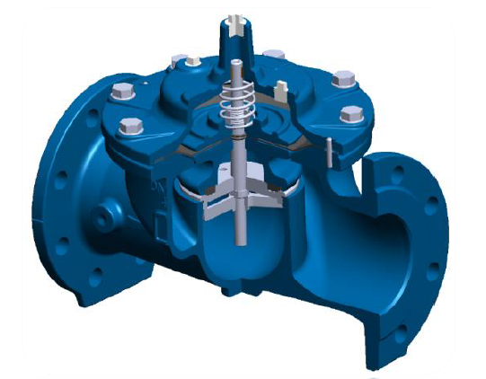
The Model GF 900 is a hydraulically operated, diaphragm actuated, globe or angle pattern valve. It consists of three major components: body, diaphragm assembly, and bonnet. The diaphragm assembly is the only moving part and is guided top and bottom by a precision machined stem.
The valve utilizes a non-wicking diaphragm of nylon fabric bonded with synthetic rubber. A resilient synthetic rubber seal matched to the seat provides a drip-tight seal when pressure is applied above the diaphragm.
It is the valve of choice for system applications requiring remote control, pressure regulation, solenoid operation, rate-of-flow control, liquid level control or check valve operation. The rugged simplicity of design and packless construction assure a long life of dependable, trouble-free operation. It is available in various materials and in a full range of sizes, with threaded, flanged or grooved ends.
Connection Standard
- ✓Flanged: ISO 7005-2 (ISO 10, 16 & 25)
Water Temperature
- ✓0 – 80°C
Working Pressure
- ✓ISO PN 16: 16 bar
- ✓ISO PN 25: 25 bar
MATERIALS
Component materials and standards (Bill of Materials).

REDUCED BORE
Cross-sectional view of the main valve — components and assembly.

MANUFACTURING & MATERIALS
Manufacturing standards and component materials.


1. CORROSION PROTECTION
- ✓COATED INSIDE-OUTSIDE
- ✓COATED ACCORDING TO GSK
2. CERTIFICATES
- ✓DM 174 (I)
- ✓WRAS (UK)
- ✓ACS (F)
- ✓DVGW (DE) — COATING & RUBBERS
3. APPLICATIONS
WATER
4. TESTING
- ✓EN 12266-1 (ISO 5208) — PRESSURE TESTS — GRADE “A”
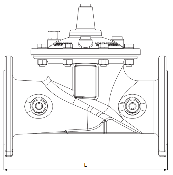
DIMENSIONS REDUCED BORE
Face-to-face and front view dimensions; dimensional data table (EN 558 S1, EN 1092-2 PN10/PN16).


DIAGRAMS
DIAGRAM FOR CAVITATION CONTROL
The diagram shows indicatively the two operating areas of the reducer, according to the applicable upstream and downstream pressures.
AREA A: continuous working conditions, no cavitation risk.
AREA B: intermitting working condition, possibility of cavitation.
Continuous working conditions in the B zone can damage the internal components more rapidly. Appropriate design precautions must be adopted if the valve works in this zone; consult technical support for detailed application guidance.
WORKING CONDITIONS LIMITS
- ✓Recommended fluid velocity upstream of the valve: for continuous service: 3.5 m/s; for peak service: 5 m/s
- ✓Minimal necessary differential pressure for the valve functioning: 0.2 bar
- ✓Working temperature: max +80°C